Luckfox Pico Mini A
Source-grounded onboarding dossier for the RV1103 board and a battery-powered smart basket prototype.
Experimental, below L0. The generic RV1103 chip and Mini A system descriptors declare CPU/memory geometry only. The separate optional
rv1103-linuxnative CLI passed a reduced direct zImage boot to real PID1 on 2026-10-12, using privileged Cortex-A7/MMU, SystemBus, GIC400, architectural timer and DW UART2. This leaves board reset, SD/vendor BSP and physical acceptance open. The olderqemu-armELF adapter remains an instruction fixture. See the Linux receipt and scope, support rubric, and validation record.
Status at a glance
| Item | Status |
|---|---|
| Exact hardware | Luckfox Pico Mini A, not Mini B |
| Vendor silicon | RV1103; Cortex-A7, up to 1.2 GHz; 64 MB DDR2 |
| Storage | MicroSD boot; Mini A has no populated SPI NAND |
| Mechanical reference | 21.00 × 28.14 mm; 2.54 mm side-pin pitch |
| Local emulator | Optional qemu-arm-system reduced Linux CLI; separate qemu-arm ELF fixture |
| Mini A target support | Below L0; reduced virtual Linux boot passed, board/BSP and physical checks pending |
Hardware facts are from the vendor variant overview, flash guide, and the drawings below.
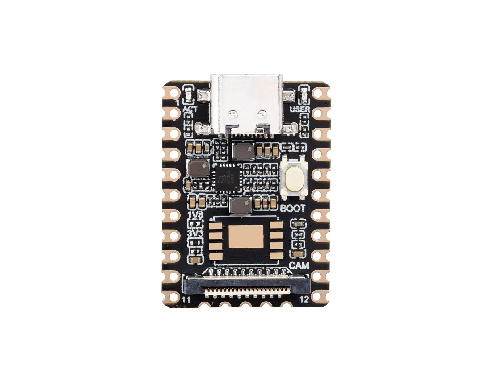
Official Mini A product photograph. Download original photograph; provenance and hashes are in the source manifest.
Flash / firmware artifact
For physical hardware, follow the vendor MicroSD flash instructions and select the Mini A MicroSD image. Record its download URL, version, SHA-256, board revision and serial boot log. No vendor OS image has been downloaded, flashed or booted as part of this dossier.
The official SDK is LuckfoxTECH/luckfox-pico. Select the RV1103 Mini board and SD-card boot with the SDK's board selector; verify the resulting device tree is for Mini A (rv1103g-luckfox-pico-mini-a.dts). The device-tree guide lists Mini A and Mini B separately. A Linux application ELF is not the bare-metal ARM instruction fixture described below.
Pins (board label → GPIO)

The vendor uses this shared Mini A/B illustration for the interface layout; its photographed board has a NAND package. It is not a photograph of the Mini A population. Download original pinout.
All 22 numbered side pads below were transcribed from this image. _d/_z suffixes are retained exactly as printed, without interpreting them as voltage ratings. Alternate functions require correct pinmux; they are not simultaneously active.
| Board pin | Printed rail / GPIO label | Alternate function shown |
|---|---|---|
| 1 | VBUS | Board supply; see power integration notes |
| 2 | GND | Ground |
| 3 | 3V3(OUT) | Output rail; do not join to external 3.3 V regulator |
| 4 | GPIO1_B2_d | UART2_TX_M1 (debug console) |
| 5 | GPIO1_B3_u | UART2_RX_M1 (debug console) |
| 6 | GPIO1_C0_d | SPI0_CS0_M0; PWM2_M2 |
| 7 | GPIO1_C1_d | SPI0_CLK_M0; PWM4_M2 |
| 8 | GPIO1_C2_d | SPI0_MOSI_M0; PWM5_M2 |
| 9 | GPIO1_C3_d | SPI0_MISO_M0; PWM6_M2 |
| 10 | GPIO1_C4_d | UART4_TX_M1; PWM8_M1 |
| 11 | GPIO1_C5_d | UART4_RX_M1; PWM9_M1 |
| 12 | GPIO1_D0_d | UART3_TX_M1 |
| 13 | GPIO1_D1_d | UART3_RX_M1 |
| 14 | GPIO1_D2_d | I2C3_SDA_M1 |
| 15 | GPIO1_D3_d | I2C3_SCL_M1; SPI0_CS1_M0 |
| 16 | GPIO1_C6_d | UART4_RTS_M1 |
| 17 | GPIO1_C7_d | UART4_CTS_M1 |
| 18 | GPIO0_A4_d | No alternate function labeled |
| 19 | GPIO4_C0_z | SARADC_IN0 |
| 20 | GPIO4_C1_z | SARADC_IN1 |
| 21 | GND | Ground |
| 22 | 1V8(OUT) | Output rail; not a battery input |
The illustration also labels ACT as GPIO3_C6_d and USER as GPIO1_A2; these are not additional numbered header pads. Five separate bottom pads carry Ethernet TXP/TXN/GND/RXP/RXN. Neither analog-input electrical limits nor output-rail current capacity can be inferred from this image.
The official schematic identifies the SARADC/PWM VCCIO2 domain as 1.8 V only. Header pads 19/20 (GPIO4_C0/C1) belong to that domain; do not apply 3.3 V or a battery voltage. The selected UART4/I2C3 connections use the separate 3.3 V domain. The schematic also requires SARADC_IN0 to remain pulled up; preserve that board function when considering pad 19. Absolute maximum ratings and ADC behavior still require the silicon documentation.
For the basket, reserve 14/15 for ADXL345 I2C3 and 10/11 for ESP-AT UART4. Optional flow control uses 17 CTS / 16 RTS. Preserve 4/5 UART2 for recovery and boot logs. See complete wiring and power notes. The vendor I2C and UART guides corroborate the Mini A/B interface selection.
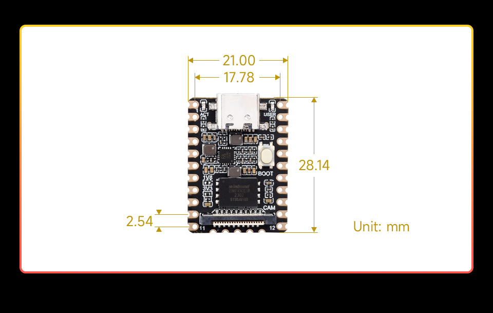
Shared vendor mechanical reference, not a manufactured carrier-board footprint. Download original dimension diagram.
Support matrix
| Capability | Status | Evidence boundary |
|---|---|---|
| Official pin / dimension / population references | ✅ | Documents and images, not electrical testing |
| Cortex-A7 arithmetic, ARM/Thumb and shared Bus access | ⚠️ | Native core fixture only; prototype scope |
| RV1103 reset, boot ROM and DDR initialization | ❌ | No board model |
| MMU, exceptions and interrupt delivery | ⚠️ | Native system fixtures and real Linux boot through GIC400; separate from old ELF adapter |
| UART2 and architectural timer | ⚠️ | Real guest console and advancing uptime through reduced SystemBus platform; functional timing |
| RV1103 CRU, reset, GPIO, pinmux and DMA | ❌ | Not modeled |
| RV1103 I2C3 connected to ADXL345 | ⚠️ | Joint real Linux transfers through modeled RK3x controller and shared ADXL345 register kit; native reduced profile only |
| ESP-AT Wi-Fi bridge | ⚠️ | Joint real guest UART4 bytes and behavioral ESP-AT mock; no ESP firmware/RF/physical proof |
| Reduced direct Linux zImage boot | ✅ | Pinned Alpine kernel/PID1/proc/mount/uname/sleep receipt; native host only |
| MicroSD controller / vendor BSP / NPU / camera | ❌ | No execution evidence |
| Battery, charging, RF and enclosure | ❌ | Engineering proposal; no bench results |
| Browser / Playground / MCP execution | ❌ | Native core experiment has no browser support |
What it catches vs bench
The reduced Linux platform catches privileged CPU, MMU, GIC/timer/console and real guest syscall integration failures. Its receipt proves cold direct zImage decompression and PID1 sleep with advancing uptime. It does not measure physical serial timing, Wi-Fi association, motion sensing, charging or battery runtime. The separate older ELF fixture exercises bounded instructions and shared memory-bus plumbing; it does not provide this Linux route.
How to run (CLI · Playground · MCP)
The chip descriptor, system manifest and example manifest declare CPU and memory geometry. They do not provide a Mini A boot/run command. For the instruction-only experiment, use the native-feature commands and receipts in QEMU ARM core prototype with examples/cortex-a7-core. Its synthetic memory map is not the RV1103 memory map. Playground and MCP board execution remain unavailable.
For the separate reduced Linux platform, follow the native zImage preparation/build/gate commands. Its backend is optional, Linux x86_64 GNU only, and requires panic unwind; default CLI and browser builds remain independent of it.
Related systems & examples
- Onboarding package and implementation gates
- Hardware, power and interface design
- Required vendor documents
- External components and model gaps
- Validation record
- Board onboarding playbook
Joint native basket evidence
The joint Linux basket receipt and reproduction add native-only ADXL345 I2C3 and behavioral UART4 integration through actual Machine/SystemBus/CosimSession plus one persistent reduced power plant. Actual 644.13082329 wall seconds / 89 functional-clock seconds at fixed 24MHz is not 1x performance. Recovery uses a fresh CPU/bus/controllers/components with the SAME plant, battery and time. Register retention applies only within one external cut/restore fixture. Raw5V maps to synthetic execution VDD; raw3V/effective external domain uses functional2.7V. Carrier disconnect and latch reset are explicit interventions. Browser/default still refuse Linux; full RV1103/vendorBSP/SD/ROM/RF/all50silicon/physical acceptance remain unavailable.