Arduino Uno R3
The classic 5 V board (A000066): ATmega328P at 16 MHz, 32 KB flash, 2 KB SRAM, an ATmega16U2 USB-serial bridge on the USB-B port, and the shield headers every other board copies. On LabWired the Uno runs real Arduino-core firmware on the AVR8 interpreter, with all three I/O ports, USART0, SPI, I2C and the ADC reaching the canvas.
Live status
The tables below are a maintained snapshot. Authoritative automation:
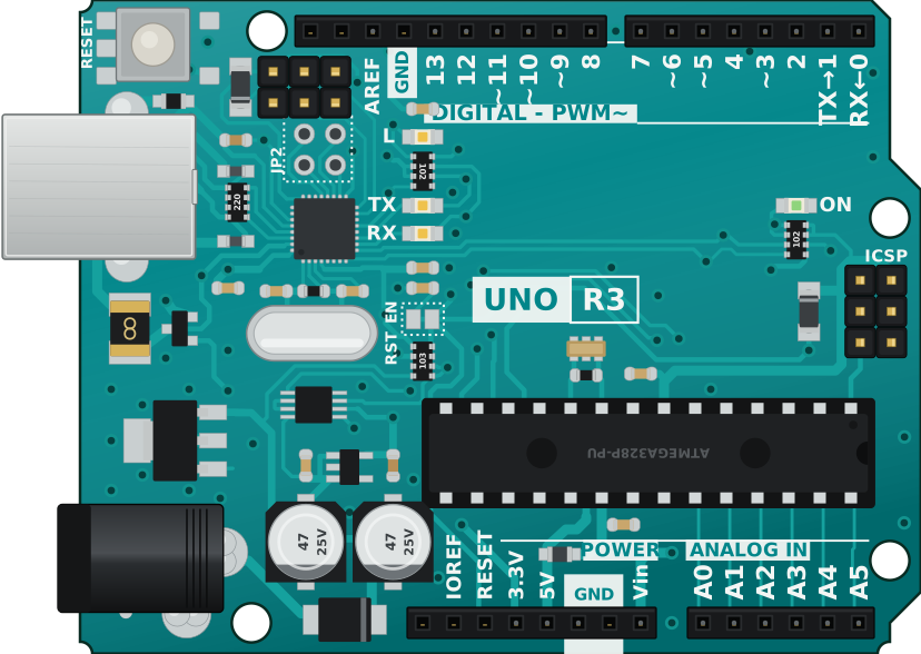
Status at a glance
| Aspect | Status |
|---|---|
| Chip descriptor | configs/chips/atmega328p.yaml |
| System YAML | configs/systems/arduino-uno.yaml |
| Examples | examples/arduino-uno-blinky/ (smoke) · examples/arduino-uno-io/ (every port) |
| Playground board id | arduino-uno |
| Hosted compile | Arduino (PlatformIO uno) and Rust (avr-none, atmega328p) |
| Tier (snapshot) | L1 smoke. Datasheet-derived. No silicon capture yet. |
The Nano (configs/systems/arduino-nano.yaml) is the same chip in the TQFP package, which adds ADC6/ADC7. Everything on this page applies to it except the header layout.
Flash / firmware artifact
| Use | Artifact | Notes |
|---|---|---|
| Twin / CLI | ELF from avr-gcc | Loaded at flash address 0. No bootloader runs. |
| Bench | HEX through the Optiboot bootloader | avrdude -c arduino -p m328p -b 115200 -P <port> -U flash:w:firmware.hex |
| Playground | Hosted compile, board arduino-uno |
Browser flashing to a physical Uno is not wired. |
Twin vs USB cable
On the Uno the USB-B cable is not native USB. The 16U2 bridges it to USART0 on D0/D1, so the serial pane and the Serial Monitor carry the same bytes.
| Twin | USB-B cable | |
|---|---|---|
| Console | USART0 TX, captured as the serial pane | 16U2 USB CDC, same USART0 bytes |
LED L |
board_io LED on PB5 (D13) |
Yellow LED on D13 |
| Load | ELF at address 0 | HEX over Optiboot at 115200 baud |
Pins
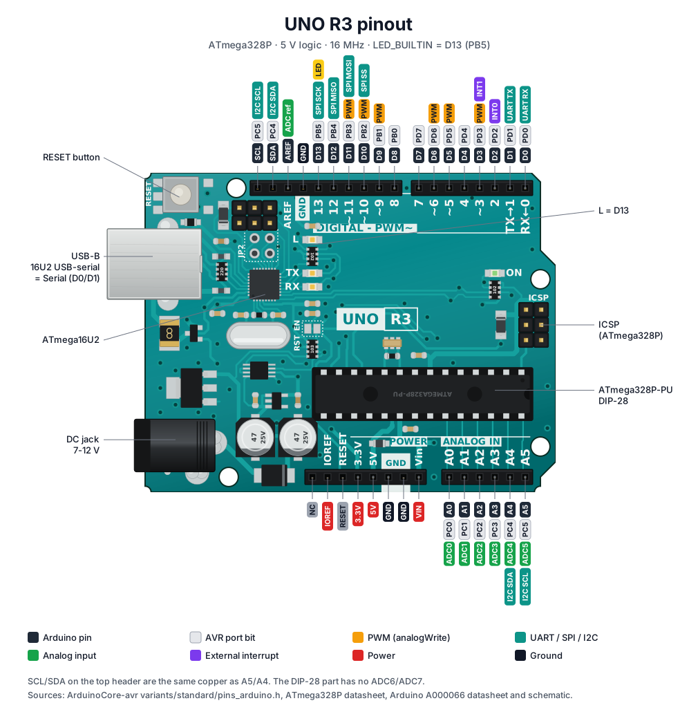
Open the pinout full size to read the tags.
Header silk and functions from ArduinoCore-avr variants/standard/pins_arduino.h
and the ATmega328P datasheet.
Digital header (top, left to right)
| Silk | Arduino | AVR | Functions |
|---|---|---|---|
| (none) | SCL | PC5 | I2C SCL. Same copper as A5. |
| (none) | SDA | PC4 | I2C SDA. Same copper as A4. |
| AREF | AREF | — | ADC external reference |
| GND | GND | — | |
| 13 | D13 | PB5 | SPI SCK, LED L |
| 12 | D12 | PB4 | SPI MISO |
| ~11 | D11 | PB3 | PWM (OC2A), SPI MOSI |
| ~10 | D10 | PB2 | PWM (OC1B), SPI SS |
| ~9 | D9 | PB1 | PWM (OC1A) |
| 8 | D8 | PB0 | |
| 7 | D7 | PD7 | |
| ~6 | D6 | PD6 | PWM (OC0A) |
| ~5 | D5 | PD5 | PWM (OC0B) |
| 4 | D4 | PD4 | |
| ~3 | D3 | PD3 | PWM (OC2B), INT1 |
| 2 | D2 | PD2 | INT0 |
| TX→1 | D1 | PD1 | USART0 TX |
| RX←0 | D0 | PD0 | USART0 RX |
Power and analog headers (bottom, left to right)
| Silk | Arduino | AVR | Functions |
|---|---|---|---|
| (none) | NC | — | Not connected |
| IOREF | IOREF | — | 5 V I/O reference for shields |
| RESET | RESET | PC6 | Active-low reset |
| 3.3V | 3V3 | — | 3.3 V output |
| 5V | 5V | — | |
| GND | GND | — | Two pins |
| Vin | VIN | — | 7-12 V input, shared with the DC jack |
| A0 | A0 | PC0 | ADC0 |
| A1 | A1 | PC1 | ADC1 |
| A2 | A2 | PC2 | ADC2 |
| A3 | A3 | PC3 | ADC3 |
| A4 | A4 | PC4 | ADC4, I2C SDA |
| A5 | A5 | PC5 | ADC5, I2C SCL |
In the Playground, every pin in the atmega328p pin bank is a wire target: D0-D13, A0-A5, AREF, 5V, 3V3, VIN and GND. SCL, SDA, IOREF, RESET, NC and the second GND are drawn as sockets but carry no wire of their own.
Support matrix
| Mark | Meaning |
|---|---|
| ✅ | Modeled well enough for the demos we ship |
| ⚠️ | Present but partial, or easy to misuse |
| ❌ | Not simulated. Use the bench. |
| Block | Twin | Notes |
|---|---|---|
| AVR8 instruction set | ✅ | Arduino-core sketches run. An unknown opcode faults instead of being skipped. |
| Flash 32 KB / SRAM 2 KB | ✅ | |
| GPIO ports B, C, D (D0-D13, A0-A5) | ✅ | Outputs reach canvas LEDs; buttons reach digitalRead. |
INPUT_PULLUP with nothing wired |
⚠️ | Reads LOW. A canvas button supplies the released HIGH level. |
Timer0 overflow (millis, delay, micros) |
✅ | |
| Timer0 compare outputs, Timer1 | ❌ | analogWrite PWM and the Servo library do not drive their pins. |
Timer2 normal and CTC (tone, noTone) |
✅ | Compare-match A/B and overflow interrupts, with Timer2's prescalers. OC2A/OC2B PWM outputs are not driven, so analogWrite on D3 and D11 still does not. |
USART0 TX (Serial.print) |
✅ | Transmit completes immediately. |
USART0 RX (Serial.read) |
✅ | UDR0 returns what a peer on usart0 sends or the host injects; RXC0 and the RX-complete interrupt work. A peer is an RS-485 transceiver with its slaves, or a UART device. No framing, parity or overrun errors. |
| SPI master | ✅ | With devices attached from the parts catalog. |
| I2C (TWI) master | ✅ | With devices attached from the parts catalog. ACK/NACK status codes follow the datasheet. |
| SPI / I2C slave mode | ❌ | |
| ADC, channels A0-A5 | ✅ | Converts the millivolts a canvas analog part drives. Unconnected channels read 512. |
| ADC bandgap (1.1 V) and REFS | ✅ | AREF is taken as 5 V; the internal 1.1 V reference is modeled. |
| ADC conversion time | ⚠️ | A conversion completes as soon as ADSC is set. |
| ADC temperature sensor | ❌ | Reads 0. |
| External interrupts INT0/INT1, pin change | ❌ | attachInterrupt never fires. |
| EEPROM | ❌ | No EECR/EEDR model and no persistence. |
| Watchdog | ❌ | |
SLEEP |
⚠️ | Treated as a no-op. The CPU does not stop. |
| ATmega16U2 USB bridge | ⚠️ | Not modeled as a chip. Its effect, USART0 on the cable, is what the serial pane shows. |
| Potentiometer part on a 5 V board | ⚠️ | The part model runs from a 3.3 V rail, so full travel reads about 675. Wire its top leg to 3.3V on the bench to match. |
What it catches vs bench
Sim is strong for: sketch logic and state machines; digital I/O on every header pin;
millis-based timing; Serial output; SPI and I2C driver bring-up against catalog parts;
analogRead against a knob or sensor; deterministic CI runs.
Still use the bench for: PWM (analogWrite) and the Servo library; interrupts on pins; serial input; EEPROM;
power, brown-out and analog accuracy; the bootloader and USB enumeration.
How to run
CLI (oracle / CI)
cargo run -q -p labwired-cli -- test \
  --script examples/arduino-uno-blinky/io-smoke.yaml \
  --no-uart-stdout
cargo run -q -p labwired-cli -- test \
  --script examples/arduino-uno-io/io-smoke.yaml \
  --no-uart-stdout
AVR firmware runs through its system manifest, which is what test --script does.
Playground
- Open app.labwired.com.
- Board: Arduino Uno R3 (ATmega328P).
- Write or paste a sketch, then Run.
- Assert on GPIO, Serial and analog inputs, not on ❌ rows.
Agent (MCP)
- Connect MCP.
labwired_describe→arduino-unooratmega328p.labwired_compile→labwired_run→labwired_verify.
Related systems & examples
| Path | What |
|---|---|
configs/systems/arduino-uno.yaml |
Board manifest |
examples/arduino-uno-blinky |
Blink and Serial smoke, board docs pack, images |
examples/arduino-uno-io |
Button on D2, LED on D7, potentiometer on A0 |
crates/core/tests/avr_uno_io.rs |
Drives each port from outside and checks what the sketch prints |
| Arduino Nano | Same chip, TQFP package |